Blower motor draw
By Steve Schaeber, MACS Technical Editor
Recently, I posted to the MACS WordPress blog and covered a fuse issue on a 1999 Volkswagen Jetta. In response to my post, I received a comment from reader Bruce Caron. Here’s an excerpt from his message:
As a former VW dealer tech, can I add a bit to your diagnosis? You would have done a better job had you, after replacement of the fuse, used an amp clamp to verify that the blower motor was not drawing an excessive amount of current. Could be maybe a dirty cabin air filter or the blower was just tired? Any time I do a blower motor or have a blown fuse, I will always check the current draw just to be sure.
So to follow up, I decided to go out and check the current draw of the blower motor on that Jetta. After all, that would be the correct way to test the system after fuse replacement and verify it’s operating properly. You may remember from the original post, the fuse was number 25, which is a 25 amp fuse. I’m not exactly sure why it blew in the first place; the system wasn’t working and replacing the fuse fixed it. I normally wouldn’t bother to find out why or verify the repair through ohmmeter testing because the vehicle is 15 years old, and sometimes fuses just blow. In this case, I know the vehicle owner installed a new cabin air filter in July, but I’m not so sure about the motor. So, I did just like Bruce suggested, grabbed my clamp amp and a few hand tools, and went out to the Jetta. Under the glove compartment door there is a soft panel that can be moved out of the way, exposing a brown wire which is the ground for the blower. Engine running, A/C on, fan on high (setting 4) and the meter measured 19.8 amps.
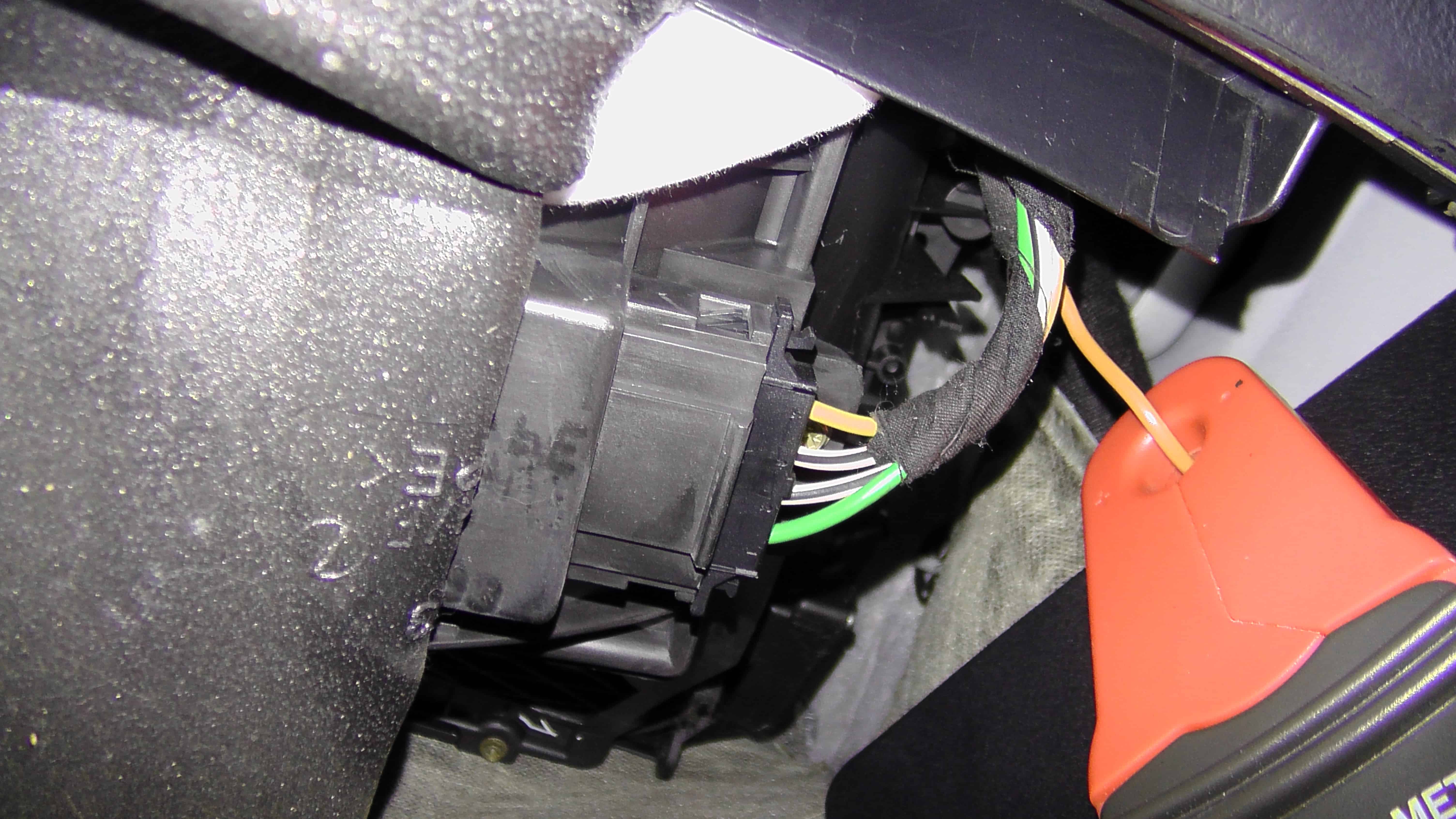
Image 1: This brown wire is used to ground this Jetta’s blower motor.
To take this diagnostic test a little further, I tested all four fan speeds under two conditions: both with the recirculation button turned on and off. I wanted to see what difference the re-circ would make, if any, but also wanted to see what the difference in current draw would be amongst the different speed settings. Here’s what I found:
Fan Speed With Recirculation Without Recirculation
4 19.8 Amps 18.0 Amps
3 11.5 Amps 10.8 Amps
2 6.8 Amps 6.5 Amps
1 3.9 Amps 3.8 Amps
There are a few things we can learn from this chart. First, at the highest fan speed setting the motor is drawing under 20 amps, which is much less than the 25 amp rating of the fuse. But this chart also tells us a few things about the relationship between blower motor speed, motor current draw and the position of the re-circulation door. Naturally, we would expect to see current draw increase as fan speed increases, but we’re seeing a larger increase when re-circulation is commanded.
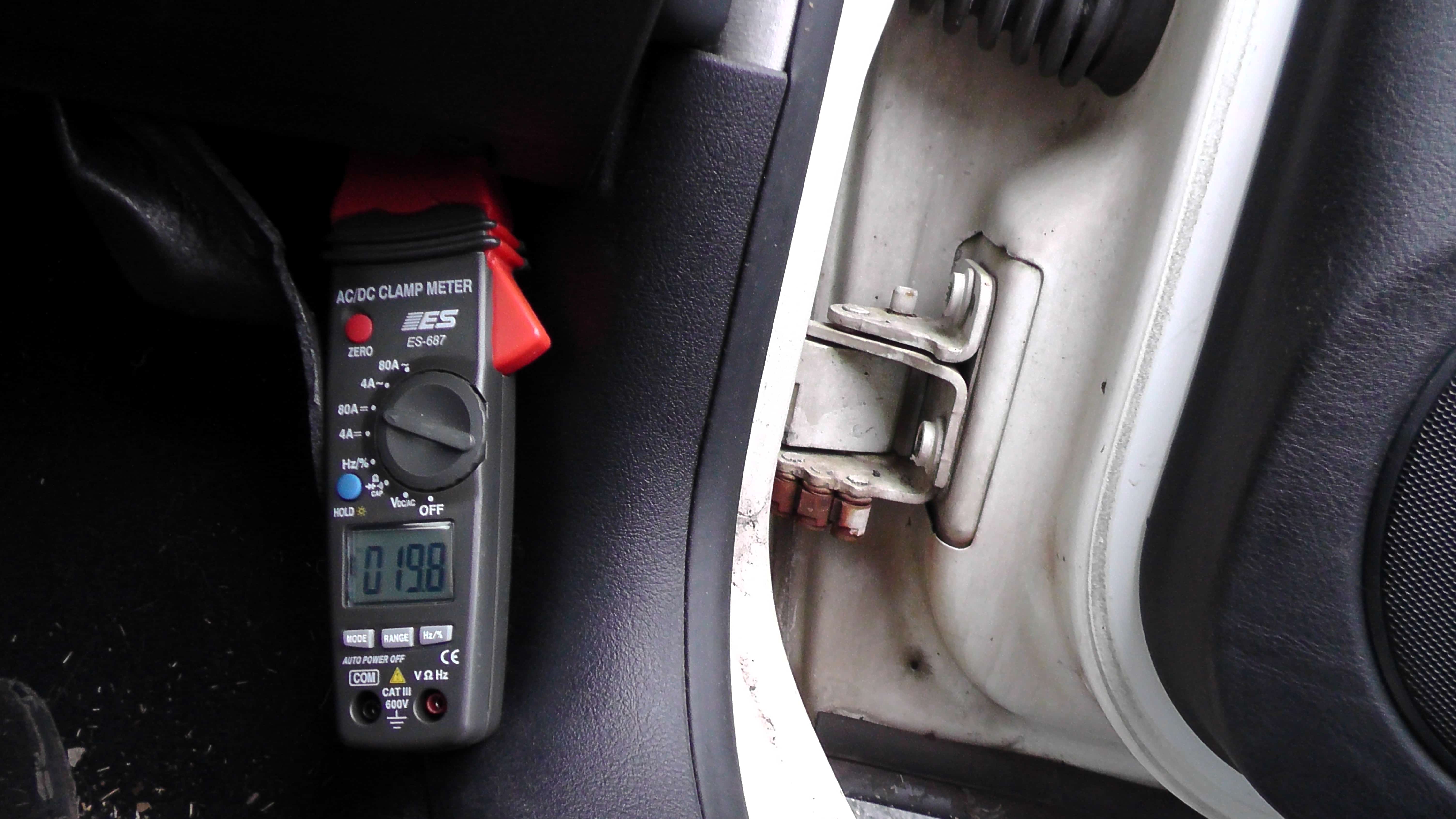
Image 2: It’s relatively easy to connect an amp clamp and measure current draw.
Blower motor amperage is not only affected by fan speed, but also by the load placed on it. The motor is turning fastest with the speed set to 4, but the motor is also working harder when recirculation is turned on, and therefore is drawing more current. That being said, why then is the current draw so much closer together at speed 1? Since the motor is turning so slowly, the application of recirculation does not cause as much of an effect on the motor’s current draw. Sure, it probably is working a little bit harder, but since it’s not moving as fast, the increase in draw is negligible.
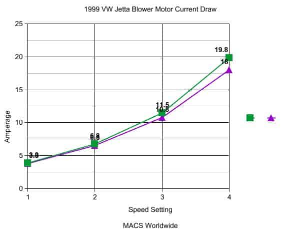
Image 3: The curve of the graph becomes more pronounced as fan speed increases in re-circulation mode.
Want to take this test a step further? Here’s a neat experiment to try: With re-circ turned on, block the air intake with an old shirt or a stiff piece of paper or cardboard, such as from a cereal box. What will happen to the amp reading?
Will it increase or decrease? You might be surprised by what you find. Respond to this blog or send an e-mail to: steve@macsw.org and let me know your results, which we’ll explore in an upcoming MACS WordPress blog.
Thanks for your comments, Bruce!
If you’re a service professional and not a MACS member yet, you should be! Become a member and receive a technical newsletter with information like what you’ve just read in this blog post visit http://bit.ly/10zvMYg for more information.
You can E-mail us at macsworldwide@macsw.org . To locate a Mobile Air Conditioning Society member repair shop in your area. Click here to find out more about your car’s mobile A/C and engine cooling system.
Mobile A/C professionals should plan to attend 35th annual Mobile Air Conditioning Society (MACS) Worldwide Training Conference and Trade Show, Meet me at MACS Make Connections that Matter, February 5-7, 2015 at the Caribe Royale, Orlando, FL.