Behavioral characteristics of various compressor types pt. 2
The last article on September 21st. featured a case study from my class held last week at the MACS Training Event & Trade Show. If you haven’t already read that article, you may want to do so. Please see picture #1.
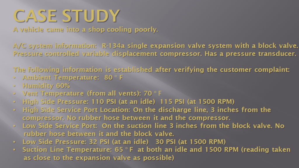
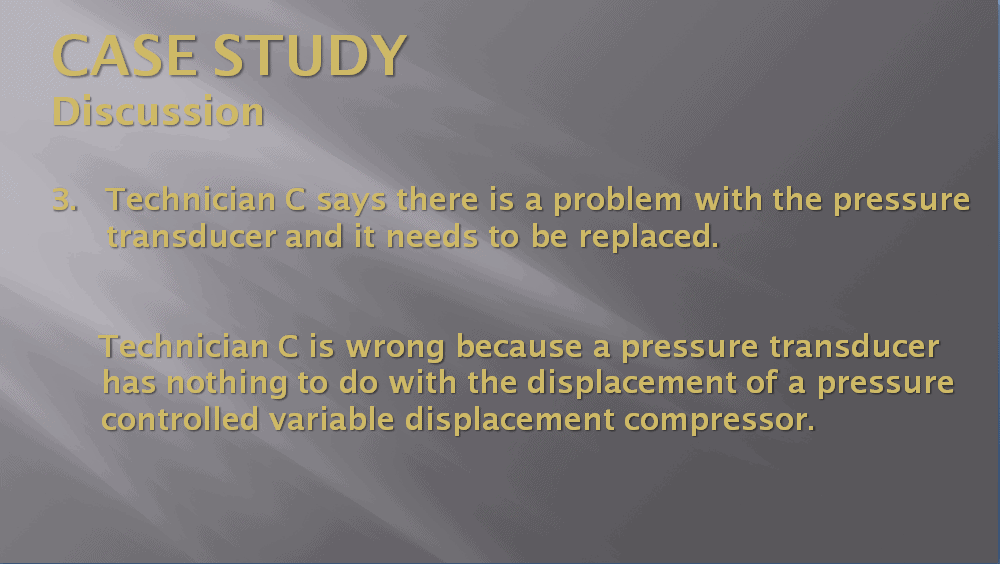
Picture #1: Case study information.
The case study was followed by four ASE test style questions. Please see picture #2.
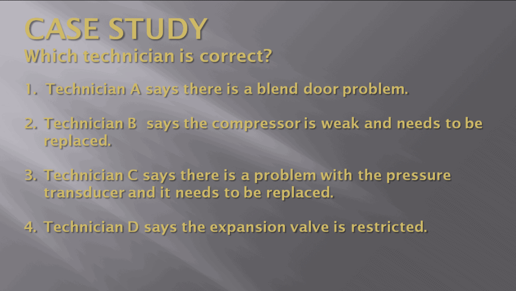
Picture #2: Case study questions:
Then there was an invitation for blog article readers to submit their answers in the “Leave a Reply” section. Please see picture #3.

Picture #3: Invitation to submit a reply.
We didn’t have anyone submit anything in the blog but did have a number of attendees in the class submit answers. Of those submitting answers in the class, about 65% submitted the correct answer. So now it is time to provide the correct answer along with information on why it is correct and also information on why the others are incorrect. We will begin with the incorrect answers. Please see pictures #4 through #8.
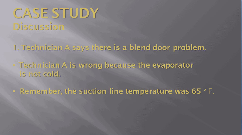
Picture #4: This is the second most often selected incorrect answer.
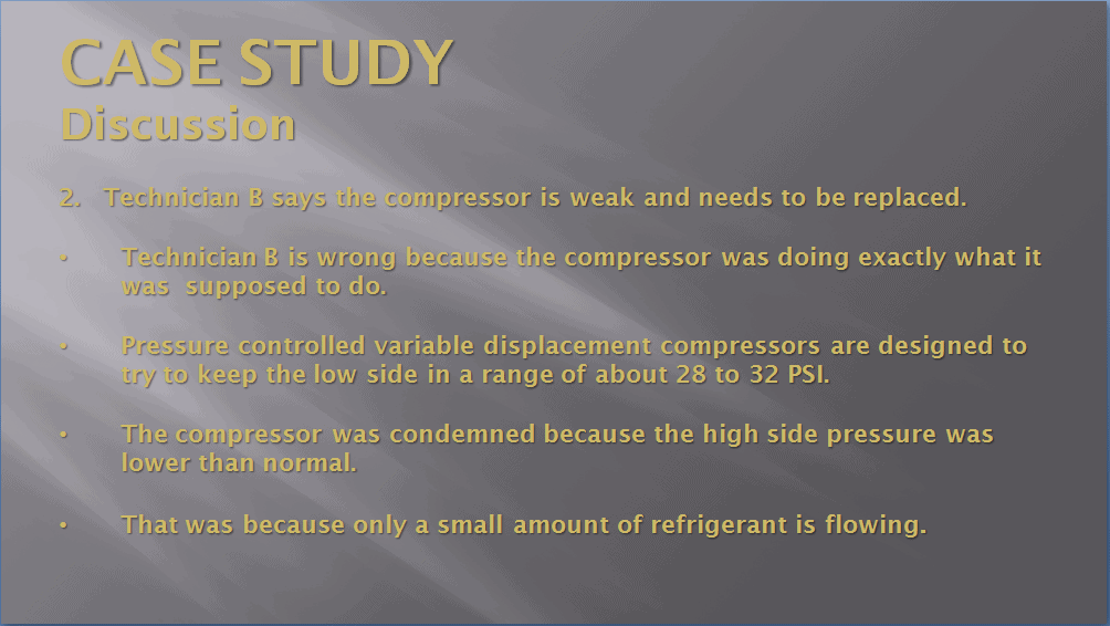
Picture #5. This is the most often selected incorrect answer.
Picture #6. This is least often selected incorrect answer.
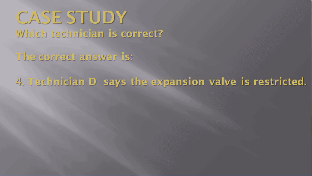
Picture #7. Finally the correct answer.
Picture #8. Even though the high side pressure is only 110 PSI to 115 PSI, the compressor is functioning perfectly.
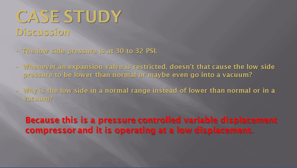
As indicated in picture #8, the compressor is functioning at a low displacement and is functioning perfectly. One might ask; how can this be? The answer is that a variable displacement compressor with a pressure control valve (aka mechanical control valve) is designed to keep the low side of a system in a range of about 28 PSI to 32 PSI. At 80° F, the static pressure (pressure with the A/C system not running) would have been about 85.5 PSI. When the compressor was turned on, it would have gone pretty close to maximum stroke initially. As the low side pressure dropped, the stroke would have decreased and when it got down to 30 PSI to 32 PSI it would have de-stroked to a very short stroke. Once stabilized, it would have remained at about that stroke.
With an ambient temperature of 80° F, it would be anticipated that the high side pressure would be in a range of about 160 PSI to 190 PSI. However, because of the short stroke and restricted expansion valve, very little refrigerant was being pumped. As a result the high side pressure was very low (110 PSI to 115 PSI). That covers what was taking place with the compressor, but there is another huge question which comes up. That question is: With a low side pressure of 30 PSI to 32 PSI, why is the suction line temperature 65° F? Please see picture #9.
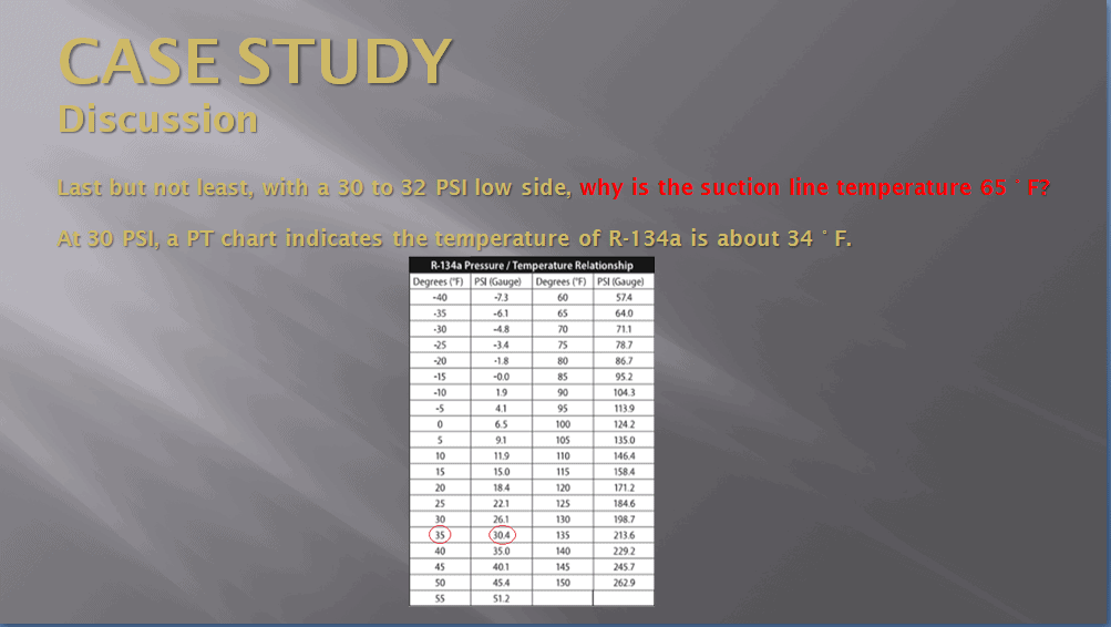
Picture #9 caption: The temperature of the suction line was taken on the metal part about 3 inches from the block valve which means it is very close to what the evaporator temperature is. A pressure/temperature chart indicates the suction line temperature and evaporator temperature should be about 34° F.
Due to space limitations, we will need to dig in to that next week.
Exceptional technical material is at the heart of MACS. To get more join MACS as a member.
Leave a Reply