Contact counts in temperature testing
By Richard Hawkins, MACS Contributor
Proper contact is vital when connecting to A/C lines using the contact type temperature thermometers. To determine if I am getting good contact, I always like to place both connectors side by side on the same line and observe the temperature readings.
Ideally since I am testing the same line in the same area, the readings should be the same. If there is a significant difference, that could indicate a contact problem. Please see picture #1 below.
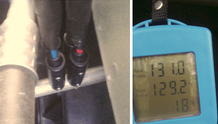
Picture #1: Both connectors placed side by side on a high sideline. The 1.8° temperature difference indicates a possible sensing element contact problem.
To determine if there is a contact problem, I need to know if the thermometer will read the same temperature on both connectors.
The first step to determine this is to conduct a test to see what the readings are on the display when both connectors are exposed to the same temperature. We need to eliminate the possibility of poor contact with the sensing element. It’s necessary to test air temperature and it should be done in the temperature ranges that will be encountered when doing temperature testing. Typically, those ranges are as follows:
About 90° to 150° for testing high side lines
60° to 80° for testing low side lines when there is a cooling problem, and the lines are not getting cold.
30° to 40° for testing low side lines under normal operation.
0°to 10° for testing when there is a problem and freezing-up is occurring.
The connectors are color coded and referred to as the red probe and blue probe on the thermometer display. In picture #2 below both connectors have been placed side by side into an oven that has been heated to a temperature of over 140°. They are not attached to anything, so they are reading the air temperature. The red probe is reading 144.5° and the blue probe is reading 144.3°. So, the red probe is reading 0.2 ° warmer than the blue probe. (Care must be exercised when doing this test so that a connector or connector wire does not meet an extremely hot surface which could damage it.)
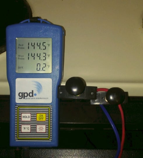
Picture #2: Both connectors placed in an oven that is heated to over 140°.
In picture #3 both connectors have been placed side by side on a sheet of paper on a tabletop at room temperature. The red probe is reading 74.6° and the blue probe is reading 74.3°. The blue probe is reading 0.3° warmer than the red probe.
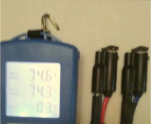
Picture #3: Both connectors placed side by side on a tabletop at room temperature.
In picture # 4, both connectors have been placed side by side in the non- frozen food storage area of a refrigerator. The red probe is reading 35.4° and the blue probe is reading 35.7°. The blue probe is reading 0.3° warmer.
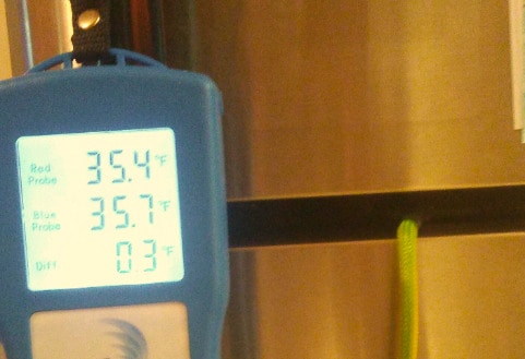
Picture #4: Both connectors placed side by side in the non-frozen food storage area of a refrigerator.
In picture # 5 both connectors have been placed inside the freezing unit. With the red probe at 5.0° and the blue probe at 5.4° the blue probe is reading 0.4° warmer.
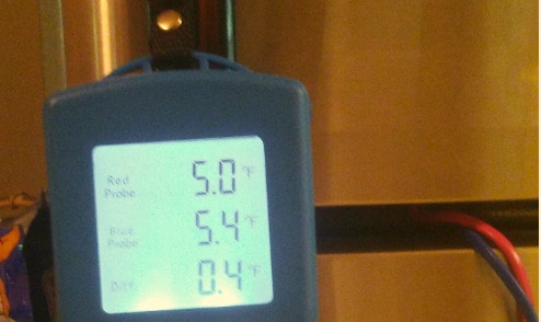
Picture #5: Both connectors placed side by side in the freezing unit of a refrigerator.
These tests involved taking a few minutes for the temperatures to stabilize. The test in the high temperature range took the longest as the temperature had to be raised from room temperature to over 140°. In the high temperature range, the red probe was reading slightly higher than the blue probe and in all three of the lower temperature ranges the blue probe was reading slightly higher than the red probe. However, all the readings were less than 0.5° so readings showing a difference of 0.5° or less when the probes are measuring the same temperature would indicate good contact.
Check back in next week and we will apply this further when connecting to lines on an A/C system.
If you like the technical content MACS supplies, why not join us as a member? We’re waiting for you!
Leave a Reply