Low refrigerant charge and the search for real data
By Richard Hawkins MACS contributor
For many years, I had read about how low refrigerant charges could increase compressor operating temperatures and decrease the amount of oil flowing to compressors, but I had never been able to find results from any tests. After discussing this with MACS, we decided to do some testing to get some real data. The event was a Temperature Testing Symposium held at the MACS headquarters.
Objectives
In addition to obtaining some definitive information about compressor operating temperatures and oil flow to the compressor, there was other information of prime interest. The following is a list of the test objectives:
- Compare the system high side and low side pressures running in a full charge condition verses an undercharged condition.
- Monitor the ambient temperature (temperature inside the shop in this case) and humidity (inside the shop in this case).
- Compare center vent temperatures running in a full charge condition verses an undercharged condition.
- Compare evaporator inlet and outlet temperatures running in a full charge condition verses an undercharged condition.
- Compare condenser inlet and outlet temperatures running in a full charge condition verses an undercharged condition.
- Compare accumulator inlet and outlet temperature running in a full charge condition verses an undercharged condition.
- Compare compressor operating temperatures running in a full charge condition verses an undercharged condition.
- Compare the amount of oil in the compressor after being run in a full charge condition verses an undercharged condition.
Equipment
To accomplish these test objectives, a manifold gauge set, and four contact type temperature testing thermometers were utilized. The contact type temperature testing thermometers were connected at the following points:
- Inlet and outlet of the evaporator.
- Inlet and outlet of the condenser.
- Inlet and outlet of the accumulator.
- Compressor case
In addition, one of the temperature testing thermometers had a probe which was inserted into the center vent inside the vehicle and another in front of the vehicle. This unit had the capability of providing the vent temperature, ambient temperature (temperature inside the shop) and humidity (inside the shop), by just pushing a button.
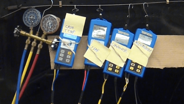
Here is the test equipment set up. The unit labeled “accumulator” also had the capability of providing vent temperature, ambient temperature (temperature inside the shop) and humidity (humidity inside the shop).
The subject vehicle was a 1998 Jeep Cherokee with a 4.0 6cylinder engine and an orifice tube system. It had a 20-ounce refrigerant capacity and 8.1-ounce system oil capacity. It had been used for some other testing which resulted in the condenser being replaced. Also, the orifice tube and accumulator were replaced, the system was flushed, and all of the oil was carefully drained from the compressor. Then 8.1 ounces of oil were added to the system and after being re-assembled and having a vacuum pulled, it was charged with 20 ounces of refrigerant utilizing a J-2788 R/R/R machine which of course has an accuracy of .5 ounces.
The next order of business was to run the A/C for an extended period of time (50 minutes) to ensure the oil was distributed throughout the system and get the compressor to maximum operating temperature, then take readings and record them.
The following system settings were used: Doors closed and windows up. High blower speed. System was run in the recirculation mode. The temperature knob was turned up slightly to provide additional heat load to prevent system cycling.
The readings were as follows: (See pictures 2 through 5)
Ambient temperature (temperature inside the shop). 89.0°
Vent temperature. 47.4°
Humidity (inside the shop). 22.4 %
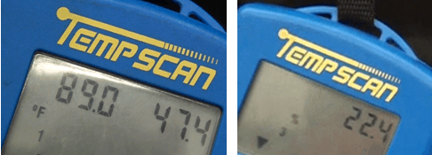
The ambient temperature (temperature inside the shop) and center vent temperature are displayed on the screen on the left side. The humidity is displayed on the screen on the right side.
System pressures. High Side: 187 PSI Low Side: 23 PSI
Evaporator inlet and outlet temperatures. Inlet: 37.0° Outlet: 36.8° (.2° differential)
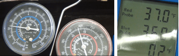
The system pressures are displayed on the left side. The evaporator temperature readings are displayed on the right side.
Condenser inlet and outlet temperatures. Inlet: 146.8 degrees Outlet: 108.6 ° (38.2° differential)
Accumulator inlet and outlet temperatures. Inlet: 39.3° Outlet: 39.3° (0° differential)
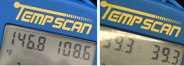
The condenser inlet and outlet temperatures are displayed on the left side. The accumulator inlet and outlet temperatures are displayed on the right side.
Compressor case temperature. 125°
The refrigerant was then recovered from the system, the compressor was removed, and the oil was drained from the compressor and measured. Quantity of oil drained from the compressor: 1.75 ounces.
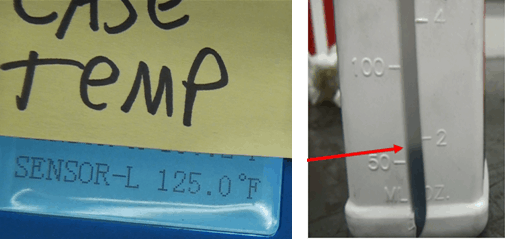
The compressor case temperature is displayed on the left side. The quaintly of oil drained from the compressor (1.75 ounces) is displayed on the right side.
Next week we will cover the results of the same tests running the system with a 25% undercharge.
What do you think of this test? Have you seen similar results? Let us know.
Leave a Reply