Low refrigerant charge and the search for real data part 4
By Richard Hawkins, MACS contributor
Fourth in a series of MACS blogs discussing low refrigerant charge and the search for real data.
When we examined the pressure readings and vent temperature readings last week, there was nothing showing up that indicated any charge issues (even operating with the 25% undercharge).
However, when we started examining temperature readings and compared them, there were several signs of problems. It is time to dig into them.
Evaporator Temperatures:
In part 1, the evaporator inlet temperature was 36.8° and the outlet temperature was 37°. That is a differential of .2° (essentially the same temperatures, as they are supposed to be on a properly charged, properly functioning orifice tube system).
In part 2, the system was run with a 25% undercharge and the evaporator inlet temperature was 34.1° and the outlet temperature was 65.8°. That is a 31.7° temperature differential, which is huge, and a sure sign of a problem. See picture #1 below.
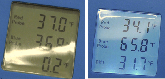
Picture #1: The readings on the left are from part 1. The readings from the right are from part 2.
So why did the 25% undercharge cause this? Because, instead of the evaporator being fully flooded with liquid refrigerant and liquid refrigerant flowing out of the outlet into the accumulator, the evaporator now had a low liquid level in it. The upper portion (probably around 35% to 40%) contained only vapor as all the refrigerant was boiling in the evaporator. This refrigerant was being superheated before it exited the evaporator which resulted in the huge temperature differential.
Another important question that needs to be asked pertains to the relationship of the evaporator outlet temperature to the vent temperature in part 2. That question is: With the evaporator outlet temperature increasing 28.7° (from 37.1° in part 1 to 65.8° in part 2), why did the vent temperature increase only .6° in part 2 (from 47.4° to 48°)?
The answer to that is the evaporator inlet temperature decreased from 37. 0° in part 1 to 34.1 in part 2 (which is a decrease of 2.9°). As a result, a large area of the evaporator (probably about 60% to 65%) was then 2.9° cooler and this was almost able to offset the higher temperature in the upper portion of the evaporator.
Condenser Temperatures:
The condenser inlet temperature in part 1 was 146.8° and the outlet temperature was 108.6°. That is a differential of 38.2° and falls right into the 20° to 50° range that is considered acceptable for a system with a fixed displacement compressor which is properly charged and operating properly. In part 2 the inlet temperature was 172.9° and the outlet temperature was 110.4° for a differential of 62.5° which of course is 12.5° more than 50°. That was another sign there was a problem. See picture #2 below.
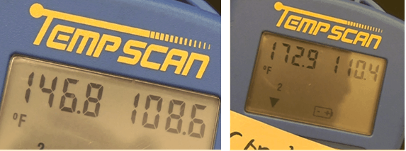
Picture #2: The readings on the left are from part 1. The readings on the right are from part 2.
Accumulator Temperatures:
The accumulator inlet and outlet temperatures were both 39.3° in part 1. The accumulator inlet and outlet temperatures were both 69.2° in part 2. There was no differential in either one.
Compressor case temperature:
In part 1, the compressor case temperature was 125.0°. In part 2 it was 152.0°. That is an increase of 27° (which is 21.6%). That may not sound like a large amount. But to put it in perspective, imagine for a moment that you have a car that runs at a constant engine coolant temperature of 200° and you’re driving down the road and look down at the temperature gauge and it is running at 242° (which is a 21% increase). That would get your attention very fast and point towards a problem. Cars of course don’t have compressor case temperature gauges, so without the special temperature probe connected to it, we would not have known this condition existed, but is certainly an undesirable thing. So that brings up the question of why did the compressor case temperature increase so much? The answer is that the refrigerant vapor flowing to it in test 1 was 39.3° and 69.2 in test 2.
That is an increase of 29.9°. We usually only think of refrigerant as being the substance which transfers heat from the passenger compartment to the condenser, but it also cools the compressor and circulates oil through the system.
See picture #3 below.
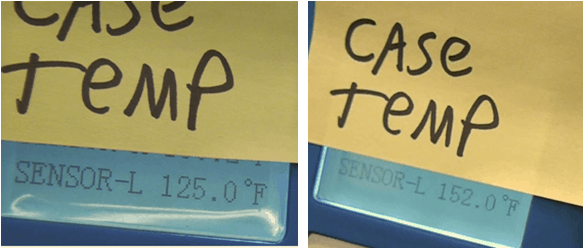
Picture #3: The temperature reading on the left is from part 1. The temperature reading on the right is from part 2.
Compressor Oil Volume:
In part 1 the quantity of oil drained from the compressor was 1.75 ounces, in part 2 the quantity of oil drained from it was .75 ounces. That is a reduction of over 57%. With the system containing a full charge of oil and the compressor containing 1.75 ounces at the beginning of part 2, that brings up an important question: What happened to that one ounce of oil? The answer is that it was retained in the evaporator. When an orifice tube system is properly charged and functioning properly, liquid refrigerant exiting the evaporator carries oil with it into the accumulator. The U tube in the accumulator has a .040 diameter drilled into it at the bottom and oil enters the U tube through the hole and vaporized refrigerant picks the oil up and carries it to the compressor. With the low refrigerant level in the evaporator, very little oil was being carried into the accumulator. See pictures 4 and 5 below.
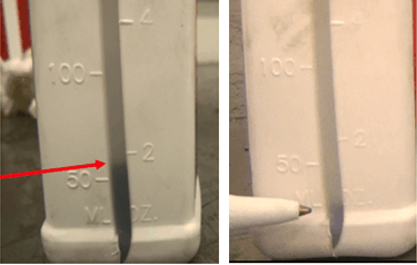
Picture #4: The quantity of oil drained from the compressor in part 1 is shown on the left. The quantity of oil drained from the compressors in part 2 is show on the right. Notice the huge difference.
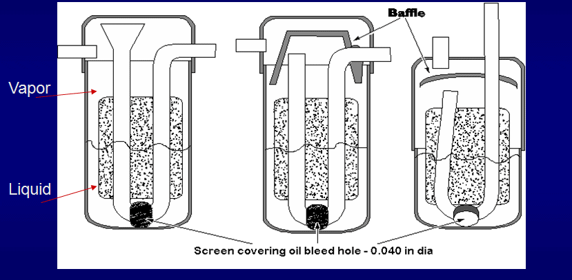
Picture #5: Here is an exploded view of 3 popular accumulator designs. In a properly charged, properly operating orifice tube system, the accumulator has vapor in the top area and liquid refrigerant and oil in the bottom (as illustrated by the squiggly line). In part 2 there would have been no liquid present and very little oil.
Content like this is very important for MACS Members. If you do not have access to real world mobile A/C service and repair content, become a member of MACS today. Join here.
Leave a Reply