Finding right side up
By Richard Hawkins, MACS contributor
In last week’s article, there was a tense confrontation between a shop owner and a technician. This happened when the shop owner informed the technician that he had installed a condenser improperly. The condenser had been installed upside down and the lines had been connected backwards.
This seemed inconceivable to the technician, and it is easy to understand why. Most condensers have different fittings on the inlet and outlet. The locations of the inlet and outlet on most condensers will not allow lines to be connected incorrectly, even if the fittings do happen to be the same size. Lastly, the designs of the mounts on most condensers prevent a unit from being installed upside down. However, none of these characteristics apply to the condenser the technician had installed. He was working on a 1998 Chevrolet C1500
General Motors used this condenser design starting in the 1994 model year. It is found on 1/2, 3/4- and 1-ton Chevrolet and GMC pickup trucks from 1994 through 1999 model years. It also appears to have been used in some ¾ and 1-ton models on through the 2002 model year.
This unit might even be found in some medium duty trucks. There were millions of these vehicles produced. From 2008 through 2019, I averaged encountering this issue probably about 6 to 8 times per year on tech calls. I probably handled a total of about 80 to 85 calls involving the issue during that time.
Vehicle owners tend to hold on to trucks longer than cars. As a result, there are still a very large number of these vehicles in use today. They don’t show up in shops as often as they used to. However, there is still a significant amount of A/C work being performed on them.
It has been almost two decades since one of these trucks rolled off the assembly line. Yet, this issue is still occurring often in 2021. Several weeks ago, I contacted three individuals who currently work on A/C tech lines. Between the three of them, they had encountered the issue over a dozen times this year.
Now it is time to look at how this occurs. The first step in the process is knowing what things are supposed to look like when the unit is installed correctly. See picture #1 below.
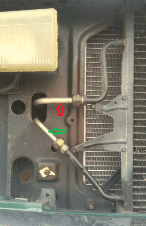
Picture #1: Here the condenser is installed in the correct position and is connected correctly. The inlet, which slightly resembles the shape of an S, is at the top. The outlet, which has a 45°bend in it, is at the bottom. The outlet contains a crimp which holds the orifice tube in place. The discharge line, running from the compressor and connected to the inlet, is noted by the red arrow. The liquid line, connected to the outlet and running to the evaporator, is noted by the green arrow. As one would expect, the discharge line is slightly larger than the liquid line.
Now we will look at what can cause the problems: First, the size of both the inlet and outlet fitting is the same. See picture #2 below.
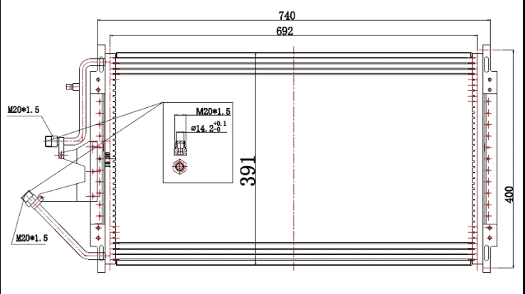
Picture #2: This engineering drawing shows both fittings as being M20*1.5 (M20 X 1.5) Drawing Courtesy of MACS Member Auto Parts Components.
Secondly, the condenser is held in place by four rubber insulators at each corner. Each corner is shaped the same and the shape inside the insulators where the corners fit is the same. As a result, the unit can easily be installed upside down. See picture #3 below.
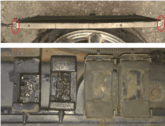
Picture #3: Notice the shape of the corners of the condenser (circled in red). The inside of the rubber insulators they fit in have the same shape. The bottom insulators are on the left. The top ones are on the right.
This is what it looks like when the condenser is installed upside down and the lines are connected backwards, as the technician had done in last week’s article. See picture #4.
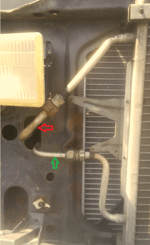
Picture #4: As can be seem from the orientation of the inlet and outlet, the condenser is turned upside down. The discharge line, running from the compressor (again noted by the red arrow) is connected to the outlet. The liquid line, running to the evaporator (again noted by the green arrow) is connected to the inlet.
With the discharge line being connected to the outlet, uncondensed high-pressure vapor from the compressor is introduced directly into the .072 inch opening in the orifice tube and that is what causes high pressure problems.
Last week I mentioned a third issue which could occur with this style condenser, but it will be necessary to keep you in suspense on that until next week due to space limitations. We will also cover what was encountered in getting those lines positioned to connect backwards.
If you like this type of high level, real-world technical content, there’s more available when you Join MACS as a member.
Leave a Reply