Field study: Incorrectly installed condensers
By Richard Hawkins, MACS contributor
I have handled numerous tech calls involving older GM trucks with incorrectly installed condensers. In preparation for this series of MACS blogs, I discovered a salvage truck with one of these condenser repairs. This gave me the opportunity to duplicate the incorrect installation and look for pitfalls and solutions.
I mentioned before the mounts are the same on all four corners. As a result, it will fit in upside down just as easily as right side up. If it is installed right side up, it requires considerable “persuasion” to connect the lines up backwards. This is because they are held in place by a bracket located behind the radiator support and they point toward the correct connections. Each line must be rotated about 45° and must be bent some to make the connections.
It is much more likely for a backwards connection to occur when the lines have been replaced, rather than with existing lines. This is because the bracket which holds them in place likely would not be tightened until they were connected to the condenser. As a result, it would not be so noticeable that new lines were not positioned correctly. See picture #1 below.
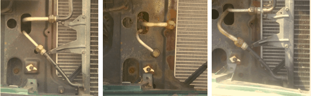
Picture #1: On the left, the condenser is in the proper position and the lines are connected correctly. In the center, the condenser has been removed. The lines are positioned just about the same as when they were when connected. They are held firmly in place by a bracket which is visible through the hole in the radiator support. On the right, the lines have been connected backwards. Notice how much each one had to be rotated to achieve this.
If the condenser is installed upside down, considerable rotating is also required to connect the lines. This is the case with them being connected correctly or backwards. There is a slight interference issue with a line nut contacting a plastic bracket located behind the headlight. However, that can be alleviated by a bit of bending of the line. See picture #2 below.
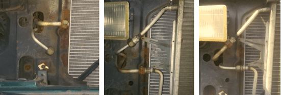
Picture #2: On the left, you can see the position of the lines after removal of the condenser. In the center, the condenser has been installed upside down and the lines are attached correctly. On the right, the lines have been connected backwards. Notice how much rotating was required to do all the connections.
Research indicates there are at least 3 versions of this condenser that have been used. The DPI numbers are listed below, with original unique characteristics noted.
4544: Used in 1994 through 1996 models. Has a crimp for the orifice tube. Has a switch port located on the outlet?
4720: Used in 1996 through 2002 models. Has a crimp for the orifice tube. Does not have a switch port.
4721: Used in 1996 through 2002 models with front and rear A/C. Does not have a crimp for an orifice tube. Does not have a switch port.
There has been some consolidation in part numbers done over the years, so some condenser suppliers may supply one unit in place of the 3. See picture #3 below.
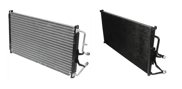
Picture #3: Research indicates that units used for the 1994 and 1995 model years had a switch port on the inlet. This was used for a switch which controlled electric cooling fans, which were optional on these models. The switch port was eliminated in 1996 and up models. With consolidations that have occurred, a unit may be supplied for a 1998 and up model that has the switch port. If that is the case, just leave the cap on it and the condenser will work fine. Photo Courtesy of MACS Member Ranshu Inc.
This style condenser is used in trucks both with front only A/C and with front and rear A/C. That presents a possibility for another issue to occur: On a front only system, the orifice tube is in the condenser outlet. When the condenser is used in a truck with front and rear A/C, the orifice tube is in the liquid line. That location is after the connection where the liquid line branches off to the rear A/C unit. Sometimes a truck with both front and rear A/C will end up with someone putting an orifice tube in the condenser outlet. That of course causes problems with the function of the rear unit. That is because the rear unit uses an expansion valve. Instead of the expansion valve being fed high pressure liquid, it is fed low pressure liquid.
There is also the possibility of someone accidently installing an orifice tube in both locations. Lastly, there is the possibility of leaving out the orifice tube altogether. With all these variables, there is a long laundry list of issues that can arise with this style of condenser.
Also, it appears that GM originally used a serpentine design condenser in these applications. Looking at various websites, it appears that it is currently available in serpentine, 6 mm, and parallel flow designs. If the replacement unit design is different from the one being replaced in the vehicle, a change in the amount of refrigerant charge is usually necessary.
If you enjoy this content and are learning from it, isn’t it time to become a MACS member? Join us here.
Leave a Reply