Compressor diagnosis
By Richard Hawkins, MACS contributor
We began this series of articles about compressor diagnosis on September 21st with a case study from the class “Behavioral Characteristics of Various Compressors” Please see picture #1.
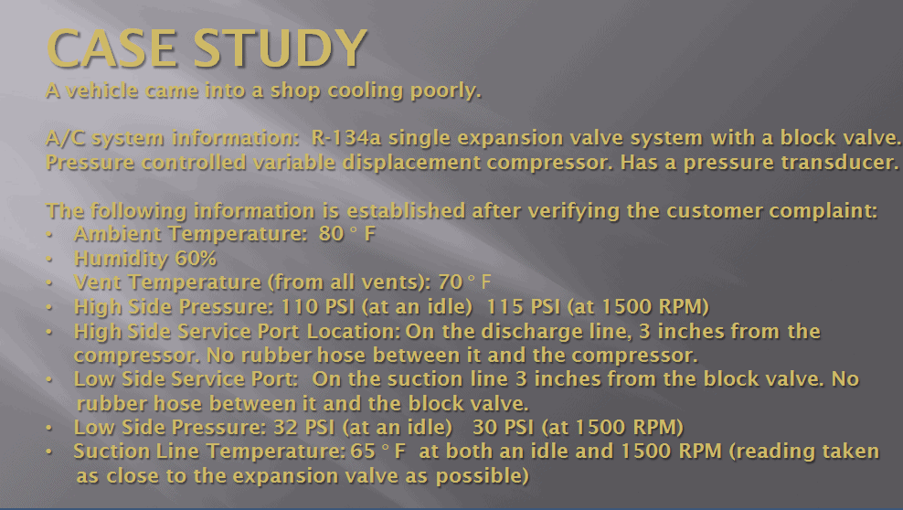
Picture #1: Case study from the September 21st article. For clarification purposes, a “pressure controlled variable displacement compressor” is one that utilizes a non-electronic control valve. It is sometimes called a mechanical control valve. Examples of these compressors would be the GM V-5, GM CVC, and Sanden SD7V16 units.
The case study was followed by 4 ASE style questions. Please see picture #2.
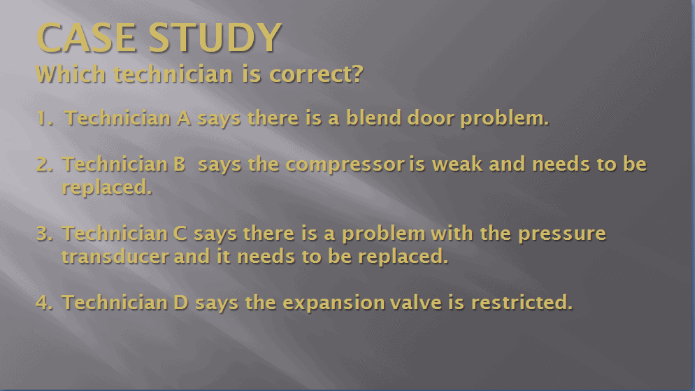
Picture #2: Case study questions.
The correct answer was Technician D. Please see picture #3.
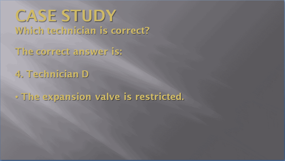
Picture #3: The correct answer.
It is important to know the correct answer, but it is more important to know why it is the correct answer.
Please see picture #4 for more information on that.
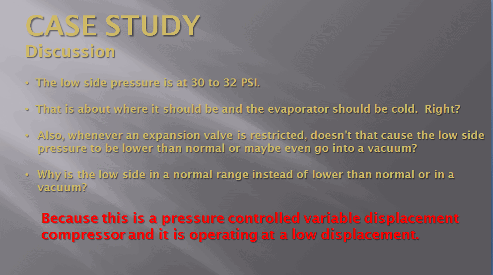
Picture #4: Even though the high side pressure is only 110 PSI to 115 PSI with an ambient temperature of 80° F, the compressor is functioning perfectly.
As indicated in picture #4, the compressor is functioning at a low displacement and is functioning perfectly. One might ask; how can this be? The answer is that a variable displacement compressor with a pressure control valve (aka mechanical control valve) is designed to keep the low side of a system in a range of about 28 PSI to 32 PSI. At 80° F, the static pressure (pressure with the A/C system not running) would have been about 85.5 PSI.
When the compressor was turned on, it would have gone close to maximum stroke initially. As the low side pressure dropped, the stroke would have decreased and when it got down to 30 PSI to 32 PSI it would have de-stroked to a very short stroke. Once stabilized, it would have remained at about that stroke.
Variable displacement compressors have been around for several decades now, but there still is a lot of mystery surrounding how they function. The GM V-5 was the first variable displacement compressor utilized in mobile air conditioning systems and it was introduced in the 1985 model year. There have been numerous other variable displacement compressors introduced since that time. Please see picture #5.
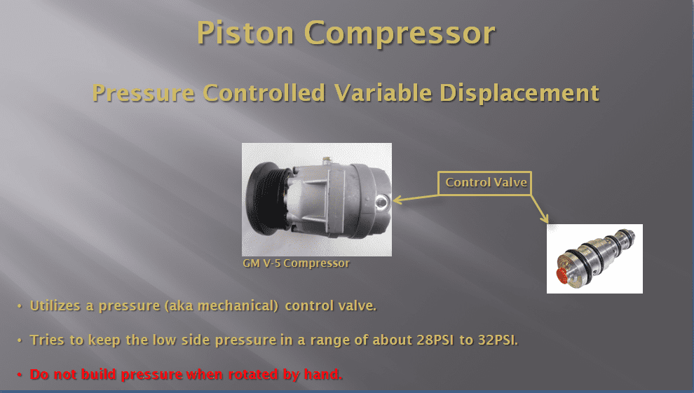
Picture #5: A GM V-5 Compressor Notice the control valve in the back of the unit. It controls displacement.
The third bullet point in the picture above states: “Do not build pressure when rotated by hand” and it is noted in red. One might ask; what is the importance of that? The importance is that frequently on tech line calls compressors are condemned when someone places their thumb over the discharge port, rotates the compressor by hand and it does not build any pressure. This occurs both with compressors which have been in use and brand-new compressors which have just been taken out of the box.
The reason these units do not build pressure when rotated by hand is:
1. They may be at an extremely low stroke.
2. They have a bleed in the control valve which allow pressure to bleed from the high side to the low side.
Now we will examine how these compressors change displacement. Please see picture #6.
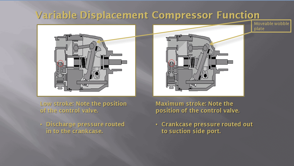
Picture #6: Notice the position of the pintle inside the control valve (circled in red). In the illustration showing low stroke, it is partially open. In the illustration showing maximum stroke, it is closed.
In picture #6 in the illustration showing low stroke, the pintle inside of the control valve is partially open. This allows high side pressure to flow into the crankcase (the area behind the pistons and around the wobble plate). You cannot see it in the illustration, but there is a bleed inside of the control valve. This bleed is there to allow pressure to bleed out of the crankcase into the suction side of the compressor. In the low stroke position, this bleed is partially open.
The positions of the pintle valve and bleed allow a significant amount of pressure into the crankcase which pushes against the back side of the pistons. This causes the movable wobble plate to move to an angle that will allow the pistons to only move about half stroke.
In the maximum stroke illustration in picture #6, the pintle is closed. This prevents high side pressure from flowing into the crankcase. The bleed is wide open. This allows high pressure in the crankcase to bleed out into the suction side of the compressor. The result is a much lower pressure in the crankcase (compared to the low stroke illustration). There is less pressure pushing against the back side of the pistons and as a result the moveable wobble plate moves to a greater angle creating maximum stroke.
A bellows inside of the control valve is exposed to the low side pressure and it contracts and expands as the low side pressure changes. When the low side pressure rises, the bellows contracts, resulting in increased stroke. When the low side pressure decreases, the bellows expands, resulting in decreased stroke. With the system stabilized, the valve is designed to try to keep the compressor at a displacement that will result in a low side pressure of about 28 to 32 PSI. A compressor like a V-5 can operate in a displacement range of from 5% to 100% and all points in between.
Join MACS as a member to learn more valuable mobile A/C technical information.
Leave a Reply