Troubleshooting the “what ifs” in a mobile A/C repair
By Richard Hawkins, MACS contributor
In last week’s article, we posed a “what if” question that involved using a different style compressor on a system that was featured in a case study the previous week. This week we will utilize another “what if” that involves two other changes to that system. First, it is necessary to recap what was done last week. Please see pictures #1 through #4.
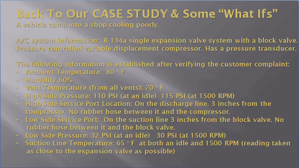
Picture #1: The case study.
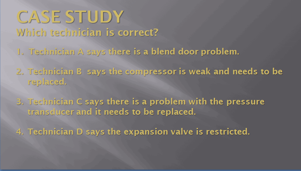
Picture #2: The case study questions.
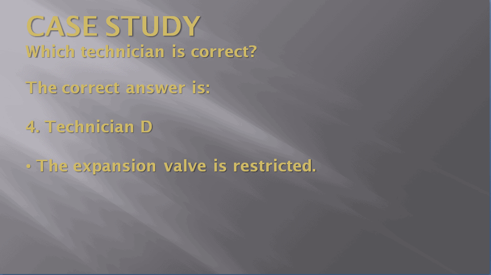
Picture #3: The correct answer.
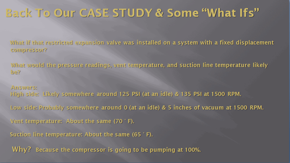
Picture #4. The “”what if” change and results.
The first change for this week will involve removing the defective expansion valve and replacing it with one which is operating properly. Please see picture #5.
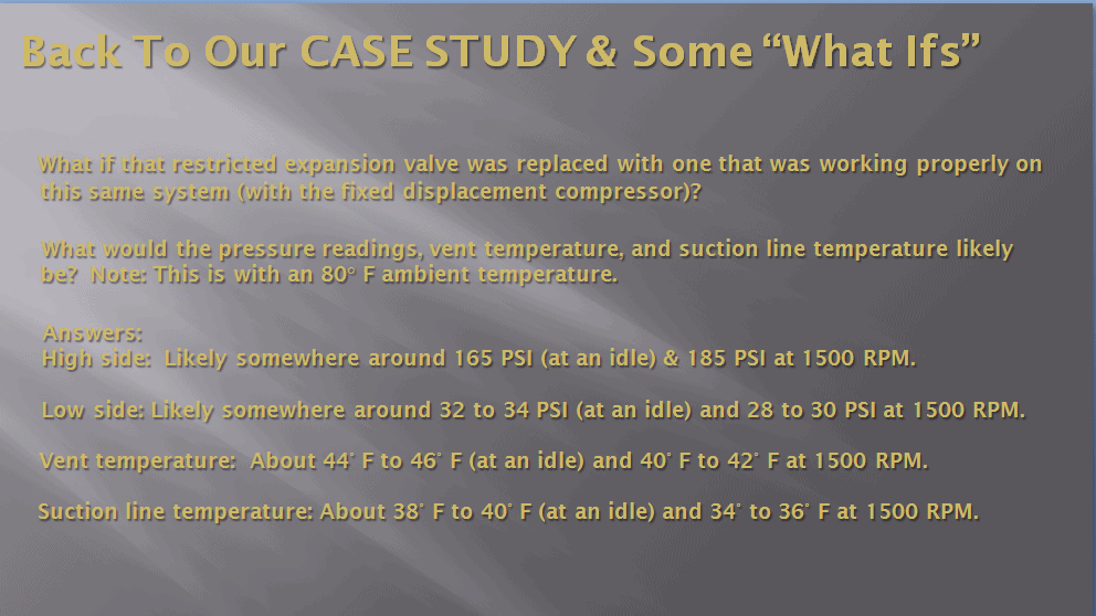
Picture #5: We now have a system which is functioning properly.
Now it is time to throw another bug in the system. Please see picture #6 for a new “what if” question.
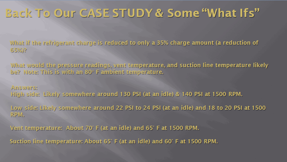
Picture #6: We have taken that system and reduced the charge by 65%.
Let’s take the results of reducing the charge and examine them.
High side: Likely somewhere around 130 psi (at an idle) & 140 psi at 1500 rpm. Why? With only a 35% charge in the system, the compressor isn’t going to be producing a lot of pressure.
Low side: Likely somewhere around 18 psi (at an idle) and 22 psi at 1500 rpm (which is about 10 psi less at both rpm levels). Why? With only a 35% refrigerant charge in the system, there won’t be a lot of refrigerant present in the low side. The expansion valve will be wide open trying to get the superheat down (which it won’t be able to do). As a result, the low side pressure will be lower (than it was with correct charge) but not nearly as low as it was with the restricted expansion valve.
Vent temperature: About 70° F (at an idle) and 65° F at 1500 rpm. Why? This is where things start to get interesting. This is because the low side pressure drops significantly, but the vent temperature increases by about 25° F. If we look at a pressure/ temperature chart (please see picture #7), a decrease in low side pressure from about 30 psi down to about 18 psi should result in an evaporator which is almost 15 degrees colder. So, this brings up the question; why did the vent temperature increase? The answer to that is that with the proper charge in the system, the evaporator likely had a liquid level of about 80% or so. With the 35% charge, the evaporator liquid level is very low (maybe only 10% to 20%). The upper portion of the evaporator does not get cold. This causes a huge amount of superheating of the refrigerant. (For more information on superheating, please click here.
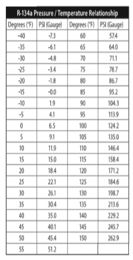
Picture #7: An R-134a pressure/temperature chart. Notice how much difference a reduction in pressure of 10 PSI to 15 PSI makes in temperature.
Suction line temperature: About 65° F (at an idle) and 60° F at 1500 rpm. Why? Because the suction line temperature will be very close to what the evaporator temperature is.
I have used this example in clinics frequently. Often someone will chime in with a statement like: With that low charge in it, that system is going to be doing a lot of rapid cycling. That is incorrect. Why? It is incorrect because we are dealing with an expansion valve system. They are thinking about an orifice tube system.
Expansion valve system compressor cycling is done based on the temperature of the upper portion of the evaporator or the temperature of the discharge air. Newer systems use either an evaporator temperature sensor which is attached to the upper section of the evaporator or a discharge air temperature which is placed in the air stream exiting the evaporator. They supply information to a computer which is programmed to cycle the compressor off and on to prevent evaporator freeze-up.
Older expansion valves systems used a mechanical temperature cycling switch which accomplished the same function. You don’t get rapid cycling with a low charge because the evaporator temperature is not going to get cold enough for the compressor to cycle off.
By contrast, most orifice tube systems use a pressure cycling switch to cycle the compressor to prevent evaporator freeze-up. (Exceptions to this would be orifice tube systems which use a variable displacement compressor and do not cycle and older orifice tube systems that used a temperature-controlled cycling switch.) The pressure cycling switches usually mount on the accumulator. They are typically designed to cycle the compressor off at about 23 psi and turn it back on at about 40 psi.
When a low refrigerant condition is encountered, the low side pressure drops very rapidly until it hits the cut-off point. Then the compressor turns off. The evaporator doesn’t have a chance to get very cold, so the pressure rises rapidly. When it reaches the cut-on point, the compressor turns back on, then the process just continues.
Note: There is some speculation involved in these answers. You never know for sure how a system is going to operate with a bug in it until you put the bug in place and run the system. However, this provides a rough idea of what could be expected.
Next week we will explore another “what if” with this case study.

Use this QR code to join MACS as a member to see even more valuable technical content.
Leave a Reply