Diagnosing electronically controlled compressors
By Richard Hawkins, MACS contributor
Continuing our discussion from last week about diagnosing electronically controlled variable displacement compressors: When preparing to conduct diagnostics on a system using one of these compressors, the diagnostic process needs to focus on four areas.
1. Does the system have sufficient refrigerant in it?
2. Is the computer command logical for the heat load?
3. Is the compressor responding properly to the computer command?
4. Is everything else in proper operating order? (Blend door operation, heater control valve, slipping belt, etc.)
Number 1 and 4 are hopefully done when conducting diagnostics on any system. Number 2 and 3 are things that someone may not be familiar with if they have not done diagnostics on one of these systems previously. As a result, we will focus on number 2 and 3. First it is necessary to understand how these compressors are controlled.
The output is regulated by the electronic control valve which is controlled by a computer through a pulse width modulation (PWM)duty cycle signal. Please see picture #1.

Picture #1: Examples of how different PWM duty cycles would appear on a scope.
Monitoring the PWM duty cycle will require the proper tool and there are several options.
1. Depending on the type, a scan tool may have the capability and of course is the fastest way to connect to the system.
2. Some aftermarket electronic compressor testing tools have the capability.
3. A scope can be used by carefully back probing the connector to the control valve and connecting the scope leads to the two wires.
4. Last but not least, a voltmeter can be used (by connecting in the same manner as the scope). The voltmeter will not provide the duty cycle, but the voltage reading can be used to provide a good idea of what the duty cycle is.
A voltmeter would be the least preferred tool but is the tool that seemed to be used most often in tech calls I was involved with over the years. This was simply because just about every shop has a voltmeter whereas they don’t necessarily have one of the other tools. Let’s take a moment to examine what happens when a voltmeter is connected to a circuit that utilizes a PWM duty cycle signal. A PWM signal is generated by a driver in a computer which just simply turns the current on and off. In the picture above, a 33% duty cycle means the current is turned on 33% of the time and off 67% of the time. A 50% duty cycle means it is on 50% of the time and off 50% of the time. A 75% duty cycle means it is on 75% of the time and off 25% of the time. This switching occurs very rapidly.
A voltmeter just takes the on and off pluses and averages them. For example, when connected to a compressor control valve circuit a reading of 6.25 to 6.5 volts would be about a 50% to 60% duty cycle. You might ask, well why wouldn’t 6.0 volts be a 50% duty cycle? That is because although automotive systems are called 12 volts systems, the charging system voltage is higher. Most of the voltage readings I have encountered on control valve circuits where the duty cycle was at 100% ranged from a low of about 12.25 volts to about 12.90 volts. A voltage reading of about 12.25 to 12.90 volts would be about a 90% to 100% duty cycle. A reading of 6.25 to 6.5 volts would be about a 50% to 60% duty cycle. A voltage reading of about 3.5 to 4.0 volts would be about a 30% to 35% duty cycle. Please see pictures #2 and #3.
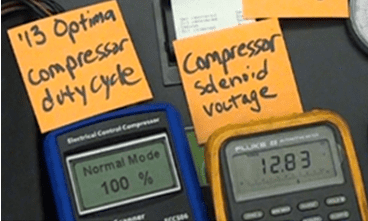
Picture #2: A system running with a high heat load at a 100% duty cycle with a voltage reading of 12.83 volts.
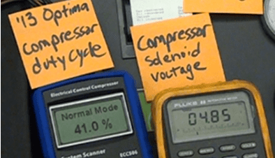
Picture #3: A system running with a low heat load at a 41% duty cycle with a voltage reading of 4.85 volts.
A high heat load should result in a high duty cycle signal going to the control valve and a low heat load should result in a low duty cycle signal going to the control valve. For example, if the ambient temperature was 80° F and a vehicle was at that temperature and you turned the A/C on, this would be a high heat load. That is because the evaporator temperature would be about 80° F and the air blowing through it would be 80° F. As a result, the computer should command the compressor to go to full output and the voltage reading should be in a range of about 12.25 to 12.90 volts.
Note: These duty cycles and voltage readings are approximate and are designed to provide a general idea of what can be anticipated testing these systems. Results can vary some from system to system.
Check back in next week and we will apply this further to diagnostic areas 2 and 3.

Use this QR code to join MACS as a member today and unlock more mobile A/C and engine cooling technical information.
Leave a Reply