The pulse width modulated duty cycle signal
By Richard Hawkins, MACS contributor
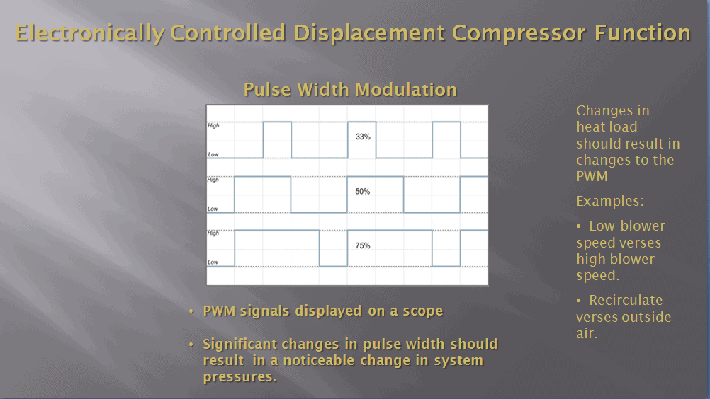
Last week we examined how the output of electronically controlled variable displacement compressors was controlled. This of course was done by a pulse width modulated (PWM) duty cycle signal supplied to the compressor control valve by a computer.
Several years ago, when vehicles using these compressors were just starting to show up at shops for service with some regularity, we were searching to find some detailed information about their behavior to use in clinics. There was not a lot of it available, so we borrowed several vehicles and did some videos. The following are some clinic slides produced from one of those videos.
This video utilized the following pieces of equipment:
- An R/R/R machine to monitor high and low side pressure.
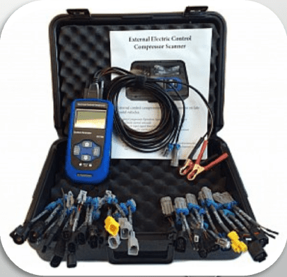
- An aftermarket “Electrical Control System Compressor System Scanner” to monitor the PWM duty cycle signal being supplied to the compressor control valve.
- A voltmeter to illustrate the correlation between the PWM duty cycle signal and voltage readings taken from the circuit supplying the PWM duty cycle signal to the control valve.
The purpose of this video was to illustrate the effects that changing heat loads had on the PWM duty cycle signal, voltage readings and system pressures. To utilize the “Electrical Control System Compressor System Scanner” we first had to disconnect the electrical connector attached to the control valve. Then the next step was to select the proper electrical adapters to connect it in-line in the circuit supplying the signal to the control valve. The voltmeter was connected to that same circuit by back probing one of the connectors with T-pins. Please see picture #1.
The “Electrical Control System Compressor System Scanner” has the capability to manually control the compressor, but in this video, it was just used to monitor the PWM duty cycle signal. The vehicle’s computer was controlling the compressor. The important thing to remember here is that changes in heat load should result in changes in duty cycle, voltage, and system pressure readings. The slides from this video do a nice job of illustrating that. Please see picture #2.
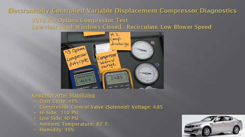
We start out by letting the system run for about 10 minutes to get the cabin air temperate down to the low 70s and the system stabilized. Please see picture #3.
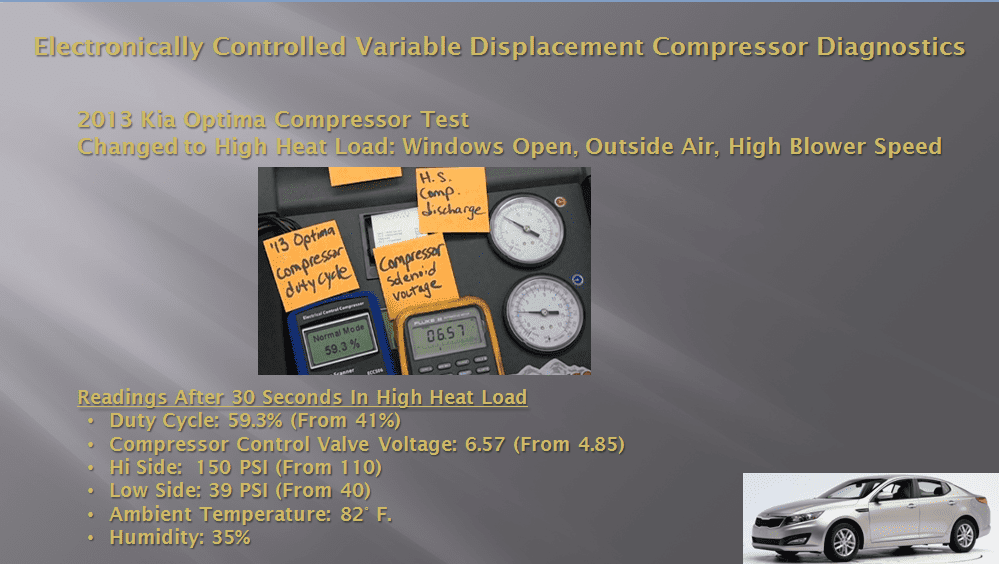
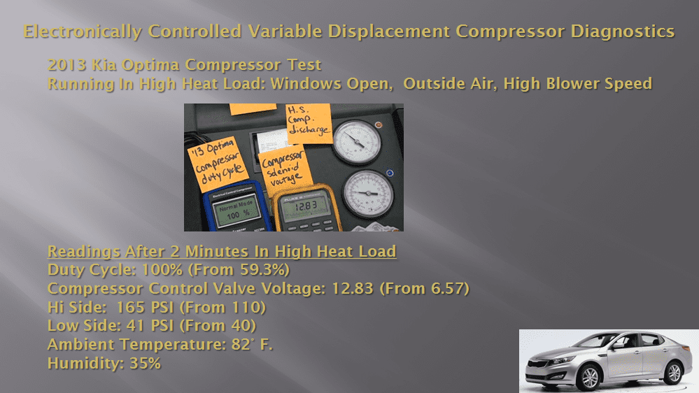
The next step was to put the system in a high heat load. This was accomplished by opening the windows, changing from the recirculation mode to outside air mode and putting the blower speed on high. The duty cycle and voltage started increasing about 10 seconds after the heat load change was made. Please see picture #4.
The duty cycle and voltage continued to increase steadily, and it took a total of about 2 minutes for the duty cycle to reach 100% and the voltage to top out at 12.83 Please see picture #5.
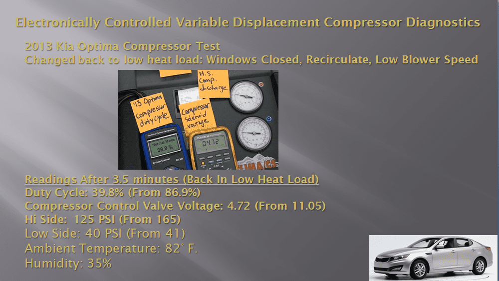
After letting the system run at 100% duty cycle for 2 minutes, the next step was to put the system back in a low heat load. This was done by closing the windows, putting the system back in the recirculation mode and putting the blower speed back on low. It took approximately 10 seconds for the duty cycle and voltage to start decreasing after this change was made. Please see picture #6.

The duty cycle and voltage continued to steadily decline. It took a total of about 3.5 minutes for the duty cycle and voltage to return to the approximate levels where we started. Please see picture #7.
To summarize:
- There was a nice steady increase in duty cycle and voltage when the heat load was increased from low to high.
- There was a nice steady decrease in duty cycle and voltage when the heat load was changed from high to low.
- There was a slow increase in high side pressure as the duty cycle and voltage increased when the heat load was changed from low to high.
- There was a slow decrease in high side pressure as the duty cycle and voltage decreased when the heat load was changed from high to low.
- Interestingly, the low side pressure did not change a great deal. It stayed in a range of from 38 to 41 PSI. It did decrease slightly when the high side pressure increased, and it increased slightly when the high side pressure decreased.
The following can be applied when doing diagnostics on one of these systems:
- If there is no change in the duty cycle and voltage when the heat load is changed significantly, then there is a problem with the compressor control system.
- If there are significant changes in the duty cycle and voltage and there is little change in high side pressures, that would indicate a potential problem with the compressor.
NOTE: Behavior can vary some from system to system, but this provides a good illustration of the effects that changes in heat load can have on duty cycle, control valve circuit voltage and system pressures.
To view the video this information came from, you can click on the following link: https://youtu.be/cVj8AMN86BU
Unbiased technical information is at the heart of the mission of MACS. Join us today as a member!

Leave a Reply