An overview of electronic variable displacement compressors
By Richard Hawkins, MACS contributor
Over the past 5 weeks we have focused on electronically controlled variable displacement compressor operation and behavior. It is important to have a good understanding of how these compressors operate and behave. This is because the percentage of vehicles coming into shops using these units is growing and will continue to grow.
The Four Seasons Division of Standard Motor Products presented a class at the MACS Training Event and Trade Show held in Orlando, FL this past fall which contained some excellent information on these units. The presentation contained an interesting slide which they made available to MACS. It indicates the mix of compressor types the OEMs have used from 1985 to 2020. Please see picture #1.
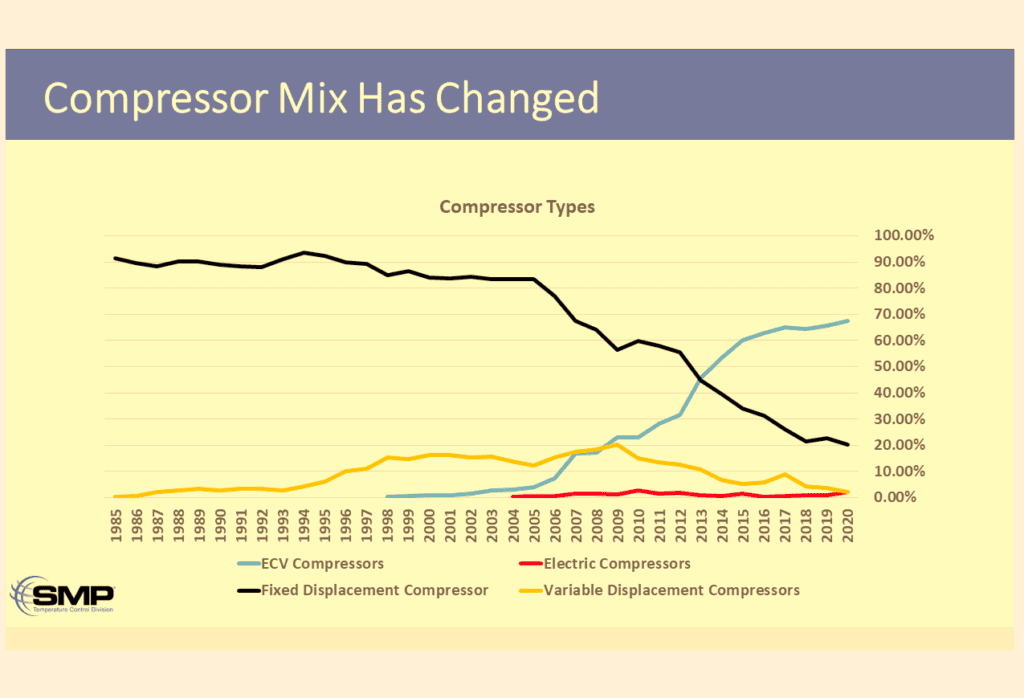
Picture #1: As indicated in the slide, use of electronically controlled variable displacement compressors (represented by the blue line) has experienced dramatic growth.
As the slide indicates, electronically controlled variable displacement compressors were introduced in 1998. It took until 2006 for them to reach a level of 10% use in new vehicles by the OEMs. Since that time there has been some dramatic growth in their use. They reached a level of 25% in 2011 and by 2020 they were the undisputed preference of the OEMs with a percentage of about 68%. NOTE: This represents use in cars, light trucks, and SUVs.
The slide also provides information on the use of fixed displacement, electric and variable displacement compressors. The “variable displacement compressors” referenced are represented by the yellow line and refer to non-electronically controlled variable compressors such as the GM V5, and Sanden SD7V16.
On a subject of a slightly different note, a reader of the December 7th article which was titled the “Pulse Width Duty Cycle Signal” posed the following question in the comments section. “Is there a difference between PWM and Duty Cycle? Or are they one and the same?” This is a good question, and we thought some other readers might have some interest in it as well, so here is some information.
PWM is a method of controlling the current being supplied to a circuit. To expand on that, the average value of voltage (and current) being fed to the load is controlled by turning the switch (driver in a computer in automotive applications) between supply and load on and off at a fast rate. Duty Cycle is a method of measuring the amount of time during each off-on cycle in a PWM controlled circuit that the power is switched on. Increasing the duty cycle increases the amount of current flow and raises the average voltage. Please see picture #2.
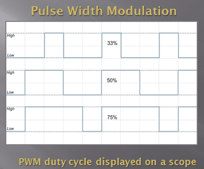
Picture #2: In these examples the 33% represents the power being tuned on 33% of the time and off 67% of the time. The 50% represents an equal amount of on-off time. The 75% represents the power being on 75% of the time and off 25% of the time. If there was a 100% line, it would represent power being applied 100% of the time, just like a headlight switch being turned on.
Using the example above: If an electric motor was being controlled by PWM and the duty cycle was increased from 33% to 50%, the speed would increase. Increasing the duty cycle to 75% would increase the speed more and increasing it to 100% would increase it to maximum speed.
Unbiased mobile A/C technical information is at the heart of MACS mission. Join MACS as member today at this link: https://macsmobileairclimate.org/membership/
Leave a Reply