Variable output scroll compressors
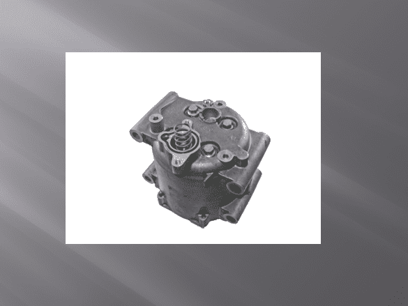
In earlier blogs, we focused primarily on compressor behavior and diagnostics. Before moving on from this subject, there is a compressor that is known for a common issue which is worthy of mentioning. There is an easy diagnostic procedure that can be used to pinpoint the problem and in a large percentage of cases the diagnostic procedure cures the problem. It is the variable output scroll compressor which is used on mid 2000s vehicles produced by Ford. Please see picture #1.
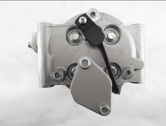
Picture #1: This compressor is easily identified by the cover on the back, attached with two bolts, which some people say resembles the shape of a football. Photo credit: Ranshu.
This compressor has been around for quite some time and the vehicles it is used on are getting some age on them. However, they still show up in shops with regularity and there still seem to be a lot of technicians that are not aware of the problem, diagnostic procedure and cure.
The usual issue is that the vehicle comes in cooling poorly. The high side pressure is lower that it should be, and the low side pressure is higher than it should be. For example, with an 85°F ambient temperature and 60% humidity, the high side will be about 145PSI to 150PSI. The low side will be about 55 PSI to 60 PSI and the vent temperature will be about 60°F. Contrast that to what you would expect to see with a properly operating system under those conditions: About 170 PSI to 200PSI on the high side, 35 PSI to 40 PSI on the low side and a vent temperature of about 45°F to 50°F. Frequently, the issue is that the compressor is pumping at a low output because the control valve which is located under the cover is not moving properly. Please see picture #2.
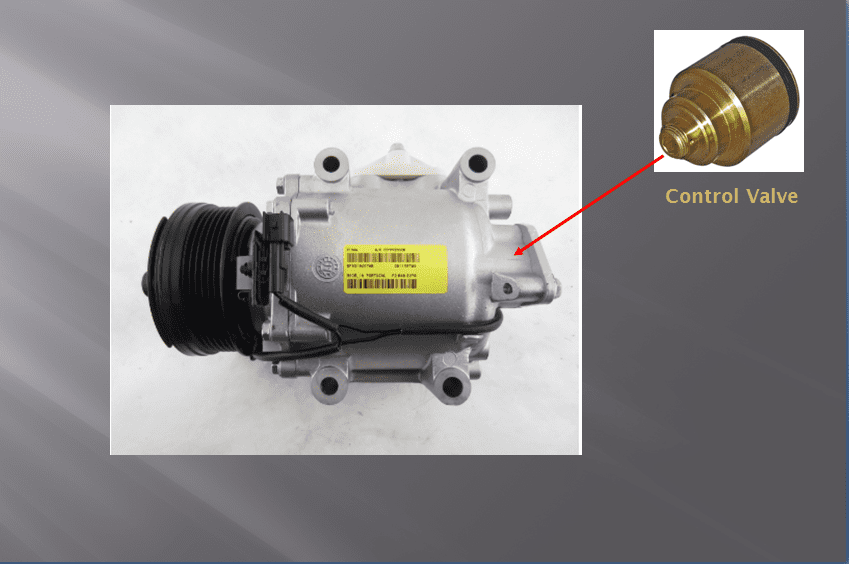
Picture #2: The control valve is located directly below the cover on the back of the compressor. Photo credit: Ranshu.
As mentioned earlier, there is a diagnostic procedure that can be done to determine if this is the problem. It involves removing the compressor control valve and spring which sits beneath it and re-positioning them.
The steps in that procedure are as follows:
1. Recover the refrigerant.
2. Remove the two bolts holding the cover. Then remove the cover. This will expose the control valve which is in the hole directly below the cover. Underneath the control valve is the spring. It pushes upward against the control valve. The pressure from the spring may be pushing the control valve out of the hole. However, if it is flush with the top of the hole, push downward on the control valve to free it up and get it to pop out of the hole. Once it is out of the hole, remove it and the spring. Please see picture #3.
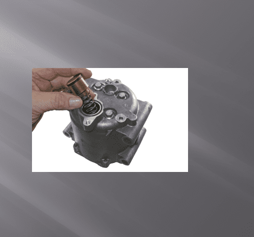
Picture #3: Removing the control valve and spring from the compressor.
3. Take a clean cloth and wipe the inside of the hole and the control valve to make sure they are clean. Then insert the control valve into the hole first (pointed in the same direction it came out). Then place the spring on top of the control valve. Take the cloth and clean the surface of the cover and the surface of the area around the control valve where the cover goes. Then replace the cover. There is an o-ring (which is shaped sort of like a pear) that goes under the cover. If possible, it is best to replace that o-ring with a new one. Please see pictures #4, 5 &6.
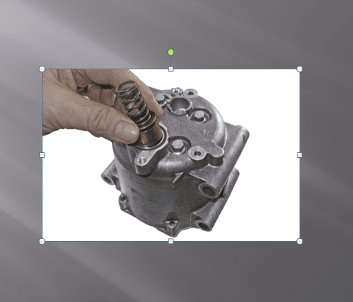
Picture #4: Insert the control valve in the hole first with it pointed in the same direction it came out. Place the spring on top of it.
Caption for picture #5. This is what it should look like when the cover is ready to be attached.
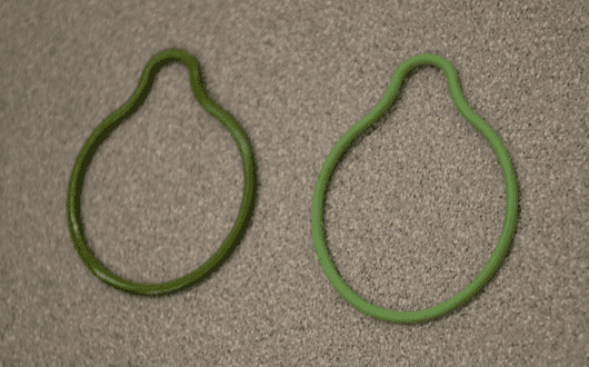
Picture #6: The “pear” shaped o-ring. Old one on the left, new one on the right.
4. Pull a vacuum on the system and then charge it back up with refrigerant. Then performance test the system and there is a very high probability that it is going to work just fine. In tech calls where I have had technicians do this procedure, that was the result 90% to 95% of the time. What has been done is that the compressor has been changed from a variable output unit to a fixed output unit and it isn’t necessary to replace the compressor. Those systems will function just fine as they have an evaporator temperature sensor which provides information to the computer about evaporator temperature. The computer will use the information to cycle the compressor to prevent evaporator freeze-up. The only downside is that with the compressor operating as a fixed output unit, there might be an ever so slight reduction in fuel economy.
Join MACS as a member to learn more mobile A/C diagnostic information.
Thanks for the article. Do you have part numbers for any of those compressors? Thanks