Avoiding Expansion Valve Woes (Part 2)
by Richard Hawkins
This is part 2 in a series of articles about avoiding expansion valves woes. If you have not already read the 1st. article, it can be found here: https://macsmobileairclimate.org/2023/03/21/expansion-valve/
That article ended with the following:
Me: That’s right. There is another problem there that needs to be diagnosed.
Check back in next week and we will discuss the most likely possible problems that would be causing the freezing up and cover the second category of expansion valve related tech calls.
Picking up where we left off
Roger: Do you think it is that evaporator temperature sensor you mentioned?
Me: There could be a problem with the evaporator temperature sensor, but there could be another issue (or issues) going on. Also, it isn’t all that likely but if there is a problem with the circuit the evaporator temperature sensor is located in, that could cause a problem. Since we’re talking about the evaporator temperature sensor, let’s address that first. Please see figure #1.
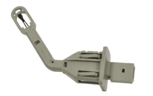
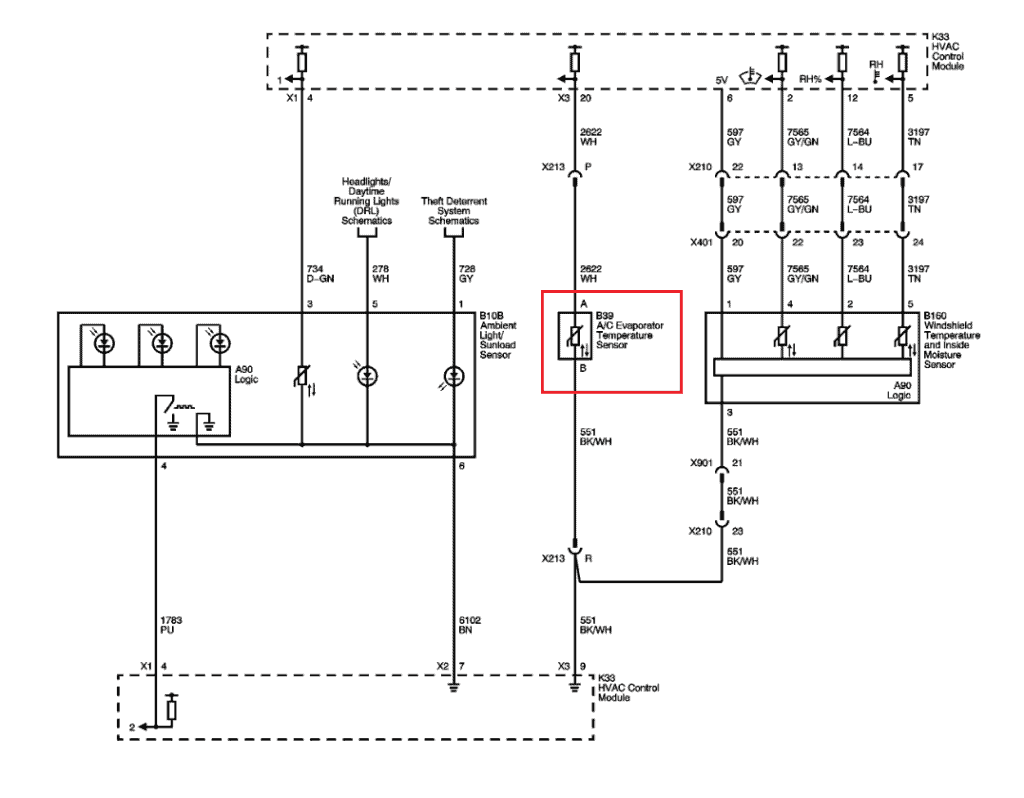
The evaporator temperature sensor is a Negative Temperature Coefficient Thermistor with two wires connected to it. The resistance of it decreases as the temperature increases. It operates in a circuit where it is supplied with a 5 volt reference signal from a computer. As the resistance changes (with temperate changes)the voltage being feed back to the computer changes. The computer reads the voltage and determines the temperature of the evaporator based on that input. A lot of OEMs will supply an evaporator temperature senor resistance chart with their service information. I’ll see if there is one listed for this car. (So I started looking in my information system.) Please see figure #2
Roger: OK I’ll check also.
Me: I found it. It includes resistance values for some other sensors too. (Roger and I had the same information systems, so I directed him to the chart.)
Roger: Thanks
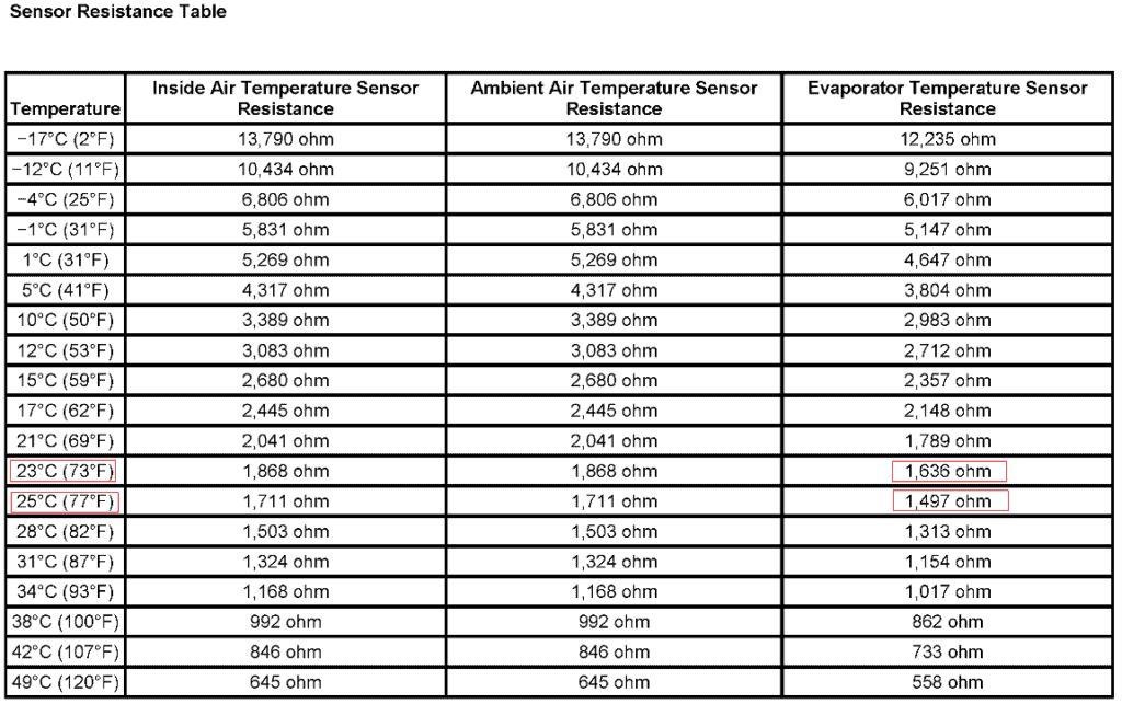
Me: The chart shows resistance information for three different sensors at different temperatures. The evaporator temperature sensor information is shown in the far right column. I’m assuming you have the car inside of the shop. What is the temperature inside of the shop?
Roger: Yes, it is inside of the shop and it hasn’t been run today. Let me take a look at a thermometer. It’s right at 75 degrees in here.
Me: OK. The chart shows 77° F and 73° F. At 77° F the chart shows a resistance value of 1,497 ohms. At 75° F the resistance is 1,636 ohms. So 75° F would fall right in between those two values. If it hasn’t been run today, it should be pretty close to the temperature in the shop. You can disconnect the connector attached to the sensor and take an ohmmeter and connect to the two terminals. At 75 degrees the resistance should be about 1,565 ohms. If for example it read 558 ohms that would definitely indicate a problem because that is the resistance valve that is shown for 120° F in the chart.
Even if it checks out close to 1,566 ohms, you should check it out further by varying the temperature of the sensor and checking it at various temperatures show on the chart. If the resistance corresponds to the values shown at the various temperatures shown on the chart, that would indicate there is not a problem with the sensor. Please see figure #3
The Sensor
As mentioned earlier, the sensor is supplied with a 5 volt reference signal. Before you disconnect the connector to the sensor to do the resistance test, check and make sure the sensor is being supplied with the 5 volt reference signal. If there is a problem with the circuit or the computer supplying the voltage, it may not be receiving the proper voltage. If that is the case, that problem will need to be further investigated.
If everything checks out with the sensor resistance tests and the sensor is being supplied with the proper voltage, then the problem with the compressor not cycling is going to lie in another area.
Roger: OK and what would those possibilities be?
Unfortunately we have run out of space. Check back in two weeks and we will address those possibilities and cover the second category of expansion valve tech calls which was referenced in the first article.
Leave a Reply