Low refrigerant charge and the search for real data: part 2
By Richard Hawkins, MACS contributor
Last week we covered part 1 of a charge test. The purpose of the test was to run an orifice tube system with a full refrigerant charge and then with a 25% undercharge and compare pressure readings and temperatures at strategic points in the system. If you haven’t already read that article, it would be a good idea to do so before continuing.
The test objectives were as follows:
- Compare the system high side and low side pressures running in a full charge condition verses an undercharged condition.
- Monitor the ambient temperature (temperature inside the shop in this case) and humidity (inside the shop in this case).
- Compare center vent temperatures running in a full charge condition verses an undercharged condition.
- Compare evaporator inlet and outlet temperatures running in a full charge condition verses an undercharged condition.
- Compare condenser inlet and outlet temperatures running in a full charge condition verses an undercharged condition.
- Compare accumulator inlet and outlet temperature running in a full charge condition verses an undercharged condition.
- Compare compressor operating temperatures running in a full charge condition verses an undercharged condition.
- Compare the amount of oil in the compressor after being run in a full charge condition verses an undercharged condition.
To accomplish these test objectives, a manifold gauge set, and four contact type temperature testing thermometers were utilized. The contact type temperature testing thermometers were connected at the following points:
- Inlet and outlet of the evaporator.
- Inlet and outlet of the condenser.
- Inlet and outlet of the accumulator.
- Compressor case
In addition, one of the temperature testing thermometers had a probe which was inserted into the center vent inside the vehicle and another in front of the vehicle. This unit had the capability of providing the vent temperature, ambient temperature (temperature inside the shop) and humidity (inside the shop), by just pushing a button.
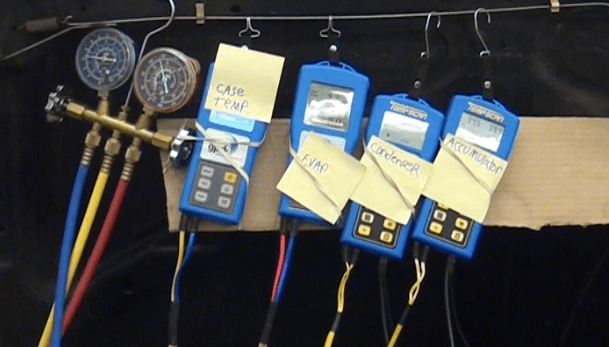
Photo #1: Here is the test equipment set up. The unit labeled “accumulator” also had the capability of providing vent temperature, ambient temperature (temperature inside the shop) and humidity (humidity inside the shop).
The subject vehicle was a 1998 Jeep Cherokee with a 4.0 6cylinder engine and an orifice tube system. It had a 20-ounce refrigerant capacity and 8.1-ounce system oil capacity. It had been used for some other testing which resulted in the condenser being replaced. Also, prior to part 1 of the test, the orifice tube and accumulator were replaced, the system was flushed, and all of the oil was carefully drained from the compressor. Then 8.1 ounces of oil were added to the system and after being re-assembled and having a vacuum pulled, it was charged with 20 ounces of refrigerant utilizing a J-2788 R/R/R machine which of course as an accuracy of .5 ounces.
After concluding part 1 of the test, we put 1.75 ounces of oil back into the compressor (which was the amount that had been drained from it), then re-installed it on the vehicle. A vacuum was then pulled on the system, and it was charged with 15 ounces of refrigerant (which is a 25% undercharge).
The next order of business was to run the system for 50 minutes as we had done in part 1 of the test. The compressor reached maximum operating temperature during this time.
The same system settings used in part 1 were used in part 2: Doors closed and windows up. High blower speed. System was run in the recirculation mode. The temperature knob was turned up slightly to provide additional heat load to prevent system cycling.
The readings from test 2 were as follows: (see pictures 2 through 5)
Ambient temperature (temperature inside the shop): 91.5° (89° in part 1)
Vent temperature: 48.0° (47.4° in part 1)
Humidity (inside the shop): 22.4 % (the same as in part 1)
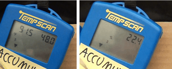
Photo #2: The ambient temperature (temperature inside the shop) and center vent temperature are displayed on the screen on the left side. The humidity is displayed on the screen on the right side.
System pressures. High Side: 185 PSI (187 PSI in test 1) Low Side: 20 PSI (23 PSI in part 1)
Evaporator inlet and outlet temperatures: Inlet: 34.1° (37° in test 1) Outlet: 65.8° (36.8 in part 1) Differential: 31.7° (.2° in part 1)
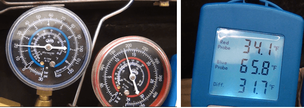
Photo#3: The system pressures are displayed on the left. The evaporator temperature readings are displayed on the right side.
Condenser inlet and outlet temperatures: Inlet: 172.9° (146.8° in part 1) Outlet: 110.4° (108.6 in part 1) Differential: 62.5° (38.2° differential in part 1)
Accumulator inlet and outlet temperatures: Inlet: 69.2° (39.3° in part 1) Outlet: 69.2 (39.3° in part 1) Differential: 0° (0° differential in part 1)
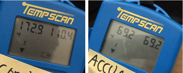
Photo #4: The condenser inlet and outlet temperatures are displayed on the left-hand side. The accumulator inlet and outlet temperatures are displayed on the right side.
Compressor case temperature: 152° (125° in part 1)
The refrigerant was then recovered from the system, the compressor was removed, and the oil was drained from the compressor and measured. Quantity of oil drained from the compressor: .75 ounces (1.75 ounces in part 1)
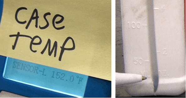
Photo #5: The compressor case temperature is displayed on the left side. The quaintly of oil drained from the compressor (.75 ounces) is displayed on the right side.
Next week we will compare, discuss and summarize the results of the testing.
MACS technical information is the real deal. If you like what you see on our blog, join MACS as a member at this link:
https://macsmobileairclimate.org/membership/
Leave a Reply